A brickobotik tinker project: the SPIKE breakout board

Guest Post by brickobotik:

LEGO Education ’s SPIKETM Prime is available on the market for more than one year by now. In our big test series, we presented in to you in detail. The Inventor 51515 which is the SPIKETM ’s home version, can also be bought by now. The software of both robots has reached a decent level. Earlier this year, we published our own e-book for the SPIKETM Prime Software that can be a helpful resource for everybody who still has questions about programming this robot. For people who like paperbacks more than digital e-books, we also sell it as a print-on-demand paperback on amazon.

At brickobotik, we nevertheless continue to work with the SPIKETM Prime. On the one hand, we use it in our workshops and teacher-trainings. On the other hand, we are also interested in the electro-technics of the SPIKETM Prime. Therefore, we give you a little insight in our „briokobotik craft corner“ and present a little project on which we currently work.

An adapter board for the ultrasonic sensor

Many of you probably noticed the two Torx screws on the back of the ultrasonic sensor in the SPIKETM Prime and the Mindstorms Inventor set which you can ‚t find on the other sensors. If you unscrew these two screws, you can remove the white ultrasonic sensor device so that only the black shell remains in your hand. Here, the cable of the LEGO Powered Up connector ends up in a female header. This 8-pin female header has a pitch of 1.27 mm which cannot be accessed easily with conventional Arduino cables. That is why we decided to develop an adapter that breaks out the 1.27 mm pitch to 2.54 mm which is the conventional dimension of the Arduino, perfboards, breadboards etc.

Technical details about the breakout board

There are six signals within the Power Functions 2.0 connection:

1x 3.3 V power supply
1x GND

 2x digital in-/output (GPIO), which can also be used for UART (115200 Baud, 8N1) Please note: The GPIOs do not supply enough current to operate the LEDs directly! A transistor circuit is necessary to supply an LED from the 3.3 V rail.

 2x PWM for the motors

Please note: The voltage of these signals is supplied directly by the SPIKE ’s battery! Aocording to our measurements it is between 8.4 V and 6.3 V.

Each GPIO signal is provided with a resistor in series that provides a minimal protection against wrong GPIO configurations. They can easily be bypassed with a solder bridge.

On the left and right side, the same signals are spread out. On one side, you find the two GPIOs together with the power rails and on the other side, you find the PWM signals with the power rails. The signal lines to the left and right do not only fan out to contacts of

2.54 mm pitch but also to contacts of 2.00 mm pitch for the Grove connector system.

The respective 3.3 V power supply lines are by default open solder bridges. In this way, two independent power supplies will not compete destructively if for example a Calliope mini or other microcontroller is used. The open solder bridges can be closed with a bit of solder if required.

New possibilities with the breakout board

With our breakout board, connecting and using other sensors and motors with the SPIKETM Prime becomes much easier. It also opens the possibility of connecting the SPIKETM to a microcontroller like the Calliope mini. But you should note one important constraint: projeots like these are primarily suitable for advanced users. The wiring as well as the programming needs experience with the electronics and the respective sensor protocols.

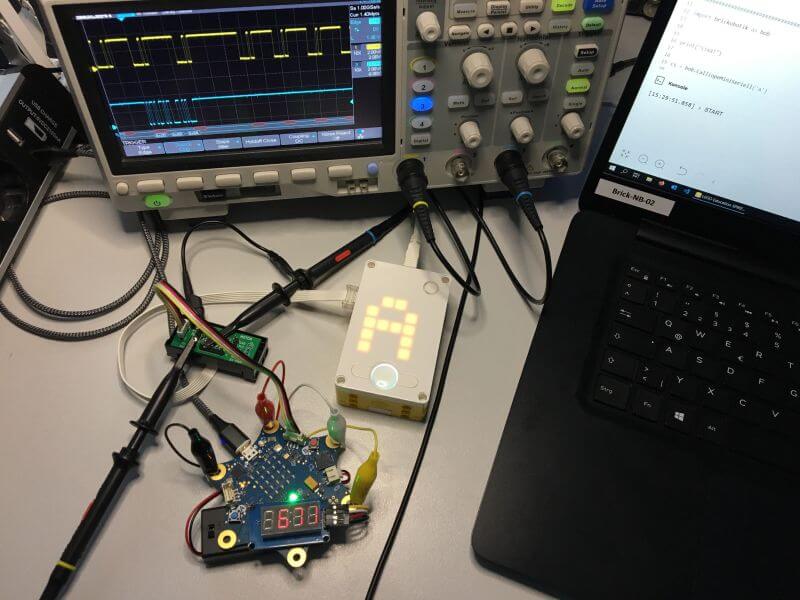
Technical details about the control

The Powered Up signals are directly controllable via the SPIKETM Prime app but only using Python projects and on one’s own account. There is no „UltrasonicBreakout“ Python module or something similar by LEGOO . Nevertheless, descriptions and instructions for the respective MicroPython classes and methods can be found in the internet. People with experience with other MicroPython devices, especially with operating the MioroPython REPL, can quickly familiarize with the necessary details.

Order your own adapter board!

At briokobotik, we are going to continue to work with the adapter board and test its conneotion to different sensors. But we would also like to give the possibility of experimenting with connections to the SPIKETM Prime to all other home constructors and electro-technios enthusiasts who like to try it themselves. So, if you are interested in this adapter board and would like to purchase it, just send us an email to [email protected]. We will collect all requests and if there are enough people interested, we will inform you via email about the possibility of preordering the adapter board.

You don ‚t want to tinker but you are interested in a certain sensor that could be conneoted to the SPIKETM Prime? Visit our website at www.briokobotik.de and leave a oomment or a message with your requests for future projects and we will try to take them into account.

Lego Mindstorms Robot Inventor/Spike Prime (51515/45678) Adapterplatine für den Ultraschallsensor

Gastbeitrag von brickobotik:

Der SPIKETM Prime von LEGO Education ist inzwischen seit über einem Jahr auf dem Markt. Wir haben ihn euch in unserem großen Test ausführlich vorgestellt. Inzwischen ist auch der Inventor 51515 also die Home-Variante des SPIKETM Prime erhältlich. Bei beiden ist die Software nun auf einem adäquaten Level angekommen. Inzwischen haben wir auch unser E-Book zur SPIKETM Prime Classroom-Software veröffentlicht, das für alle, die noch Fragen zur Programmierung der Roboters haben, definitiv einen Blick wert ist.

Für uns bei brickobotik geht die Arbeit mit dem SPIKETM Prime aber trotzdem weiter. Zum einen natürlich in unseren Workshops und Fortbildungen, die wir zu diesem Roboter durchführen. Aber auch die Elektrotechnik des SPIKETM beschäftigt uns. Deshalb geben wir euch in diesem Artikel einen kleinen Einblick in unsere „brickobotik-Bastelstube“ und stellen ein Projekt vor, an dem wir gerade arbeiten.


Viele von euch ist sicher aufgefallen, dass der Ultraschallsensor von SPIKETM Prime und Mindstorms Inventor im Gegensatz zu den anderen Sensoren auf seiner Rückseite zwei Torx-Schrauben zeigt. Wenn man diese herausschraubt, kann man die weiße Sensoreinheit des Ultraschallsensors entfernen und hält dann nur die schwarze Schale in der Hand. Darin kommt das Kabel des LEGO Powered-Up-Steckers an und wird auf eine Buchsenleiste verteilt.

Diese Buchsenleiste (es handelt sich um einen 8-Pin Female Header) ist mit einem Rastermaß von 1,27 mm sehr klein und es kann deshalb ziemlich fummelig werden, sie mit herkömmlichen Arduino-Kabeln zu nutzen. Darum haben wir eine passende Adapterplatine entwickelt, welche die kleine Buchsenleiste auf das typische Rastermaß von 2,54 mm übersetzt, wie man es vom Arduino, Steckbrettern, Lochrasterplatinen, etc. kennt.

Technische Details zur Platine

Die Power-Funotions-2.O-Verbindung führt sechs Kontakte:

1X 3,3 V Spannungsversorgung
1X GND
2 digitale Ein-/Ausgänge (GPIO), welche auch für UART (115200 Baud, 8N1) verwendet werden können.
Achtung! Die GPlOs liefern nicht genug Strom, um LEDs direkt zu betreiben! Es wird eine Transistorschaltung benötigt, um eine LED aus der 3,3 V Spannungsversorgung zu speisen.

2x PWM für Motoren

Achtung! Die Spannung dieser Signale kommt direkt vom Akku des SPIKETM Prime! Diese liegt nach unseren Messungen zwischen 8,4 V und 6,3 V.

Für die GPlO-Kontakte ist auf der Platine je ein Widerstand vorgesehen, welcher einen minimalen Schutz gegen falsche GPlO-Konfigurationen darstellt. Sie können aber auch einfach überbrückt werden.

Nach links und rechts sind die gleichen Kontakte noch einmal ausgeführt. So sind auf der einen Seite der Platine die GPlO-Kontakte mit Spannungsversorgung ausgeführt und auf der anderen Seite die PWM-Kontakte mit Spannungsversorgung – und zwar sowohl im Rastermaß 2,54 mm als auch im Rastermaß 2,00 mm für das Grove-Stecksystem. Für die Kontakte links und rechts ist die Spannungsversorgung von 3,3 V durch eine offene Lötbrücke unterbrochen, damit zum Beispiel bei Verwendung eines Calliope mini die unabhängigen Spannungsversorgungen beider Geräte nicht zerstörerisch konkurrieren. Die offene Lötbrücke kann bei Bedarf mit etwas Lötzinn geschlossen werden.

Neue Möglichkeiten durch die Platine

Mit der Platine ist es deutlich einfacher, weitere Sensoren oder Motoren anzuschließen und mit dem SPIKETM Prime zu nutzen. Auch eine Verbindung zu Mikrocontrollern wie dem Calliope mini ist möglich. Aber es gibt eine wichtige Einschränkung: Solche Projekte sind eher für fortgeschrittene Nutzer*innen geeignet. Sowohl die Verdrahtung als auch das Programmieren erfordern Erfahrung mit der Elektronik und den entsprechenden Sensorprotokollen.

Technische Details zur Ansteuerung

Das direkte Ansteuern der Kontakte funktioniert über die SPIKETM-Prime-App, allerdings nur in Python-Projekten und auf eigene Faust. Es gibt kein von LEGO gestelltes „UltrasonicBreakout“ Python-Modul o.ä. Beschreibungen und Anleitungen zur den entsprechenden Micropython-Klassen und -Methoden kursieren jedoch im Internet. Wer Erfahrung mit anderen Micropython-Geräten, speziell der Bedienung der Micropython-REPL, mitbringt, kann hier schnell Fuß fassen.

Bestellt eure eigene Adapterplatine!

Wir werden bei brickobotik mit der Platine weiterarbeiten, um die Verbindung mit verschiedenen Sensoren zu testen. Allen Bastler*innen, die jetzt Lust bekommen haben, ebenfalls mit Verbindungen zum SPIKETM Prime zu experimentieren, möchten wir die Möglichkeit geben, unsere Adapterplatine dafür zu nutzen. Wenn ihr also Interesse an der beschriebenen Platine habt und sie über uns erwerben wollte, dann schreibt uns eine E-Mail an [email protected]. Wir sammeln die Anfragen und wenn genügend Interessent*innen zusammenkommen, geben wir euch per Mail Bescheid, sobald die Platine vorbestellbar ist. Du willst nicht selbst basteln, bist aber interessiert an einem bestimmten Sensor, den man mit dem SPIKETM Prime verbinden könnte? Dann besuch uns auf www.brickobotik.de und lass uns einen Kommentar oder eine Nachricht mit deinen Wünschen da. Wir werden versuchen, sie für kommende Projekte zu berücksichtigen